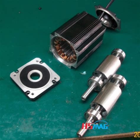
Permanent magnet rotor e1655961736623.jpeg.
An ironless rotor structure wastes permanent magnet material, since the magnetic circuit closes through air in the rotor side. Therefore, a thin steel rim, to which the magnets are attached, is employed (Fig. 9.1) The rim can be either a laminated structure, in which case the eddy current losses of the rotor remain
2.2 External rotor permanent magnet motor rotor air gap magnetic field When the motor is running at no load, the air gap magnetic field is provided by the permanent magnet alone. The generated magnetic field rotates together with the rotor and the rotational speed is synchronous speed.In order to address these issues, a 2-DOF surface permanent magnet spherical motor with a new mechanical design for the movement of the rotor with a large tilt angle of ±45° was designed, simulated, produced and tested in this paper. The motor consisted of a 4-pole permanent magnet rotor and a 3-block stator with 18 coils.Permanent magnet traction motor has the advantages of high efficiency, high power density, high torque density and quick dynamic response, which has been widely used in the traction field of electric vehicle. The high-performance control of permanent magnet traction motor depends on accurate rotor position information, which is usually …Lee et al. (5, 6) proposed a rotor supported by the permanent/electromagnetic magnetic bearing (PEMB) to operate well under the control of four simple analog PD controllers. In this study, the design considerations of the PEMBs and the method for analyzing the complete rotor-bearing system are presented. Also, a …
2.2 External rotor permanent magnet motor rotor air gap magnetic field When the motor is running at no load, the air gap magnetic field is provided by the permanent magnet alone. The generated magnetic field rotates together with the rotor and the rotational speed is synchronous speed.
For high-speed permanent magnet synchronous motors (HSPMSM), the rotor eddy current loss is generated by the time and the space harmonics, which results in the rotor temperature rise. This paper deals with the design and analysis of a 100kW, 20000r/min HSPMSM with novel composite rotor. The novel composite rotor includes a shaft, …
An interior permanent magnet synchronous motor (IPMSM) with ‘VV—’ shape rotor topology structure is proposed. The established two-dimensional (2D) parameterized finite element analysis (FEA) models are used to analyze and compare the output average torque, torque density, air-gap flux density and back electromotive force …For high-speed permanent magnet synchronous motors (HSPMSM), the rotor eddy current loss is generated by the time and the space harmonics, which results in the rotor temperature rise. This paper deals with the design and analysis of a 100kW, 20000r/min HSPMSM with novel composite rotor. The novel composite rotor includes a shaft, …In a permanent-magnet machine, where the magnets reside on the rotor, there is no secondary winding. However, the permanent magnet can be modeled with a fictitious secondary winding excitation [1,2] and therefore the stator leakage inductance can be defined. Care must be taken that permanent magnets do not get demagnetized due to excessive ... Jun 23, 2022 · The rotor overtemperature caused by losses is one of the important issues for the high-speed electrical machine. This paper focuses on the rotor loss analysis and CFD-thermal coupling evaluation for 105 kW, 36,000 r/min HSPMSM. Three types of sleeve materials as carbon-fiber, Titanium alloy, and stainless steel are introduced in this paper, researching the effects of sleeve conductivity ... addition to the magnet torque, thus improving the efficiency. In addition, the IPMSMs provide more rotor robustness as magnets are embedded in the rotor laminations; hence, no additional retention sleeving is required. Various IPMSM technologies have been studied in the literature. In [3], the V-shape, the U-shape, the spoke-type and the
Today’s automotive industry has focused its studies on electric vehicles (EVs) or hybrid electric vehicles (HEVs) rather than gasoline-powered vehicles. For this reason, more investment has been made in electric motors with high efficiency, high torque density, and high-power factor to be used in both EVs and HEVs. In this study, an outer-rotor …
Based on the complex structural characteristics of permanent magnet-assisted synchronous reluctance motors (PMA-SynRMs), this paper proposes a multi-objective optimization design method for the motor using a composite algorithm. Firstly, the power density, electromagnetic torque, cogging torque, and torque fluctuation coefficient …
Jul 1, 2017 · Unbalanced magnetic force (UMF) is one of the most important issues in permanent magnet (PM) machines with rotating asymmetric winding configurations, where the UMF is intrinsic [1, 2]. When these machines are perfectly manufactured, they show good electromagnetic performances such as high efficiency, high torque density, low torque ripple and ... 1,416 permanent magnets stock photos, 3D objects, vectors, and illustrations are available royalty-free. See permanent magnets stock video clips. Experimental electric generator on white background, consists of copper coils and magnets. A generator is a device that converts mechanical energy to electrical energy for use in an external circuit. A method of balancing an embedded permanent magnet motor rotor includes the steps of: a) providing a non-magnetic cylindrical shaft having an axis of rotation and a generally cylindrical surface with an even number of recessed slots defining an even number of ribs therebetween; b) machining an axial slot having a cross-section with a top opening, a bottom and two sides in a center portion of ... 1 Introduction. Nowadays, high-speed surface-mounted permanent magnet synchronous machines (SPMSMs) are becoming more and more common due to their simple structure, high-power density and high efficiency [1-3].The rare-earth permanent magnets (PMs) are widely applied in the high-speed SPMSMs owing to their high …A magneto-structural combined dimensional and topology optimization approach for interior permanent magnet synchronous machine (IPMSM) rotor design is proposed using the solid isotropic material with penalization (SIMP) density-based topology optimization method. This method optimizes the location and dimensions of the …
Magnetization process for PM rotors. The Permanent Magnet (PM) motor is a critical part in many electric car powertrain designs, which is undergoing rigorous improvement and changes. PM motors offer compact design and higher system efficiency among other advantages. The race for the electric cars has begun in the automotive industry and ... Apr 5, 2022 · This type's rotor interacts with the stator's RMF exactly the same as a permanent-magnet rotor, but the rotor lacks permanent magnets. Instead, it features six broad copper lobes energized with DC ... Non−Magnetic Rotor Core Rotor Magnets Rotor Pole Pieces Figure 2: Axial View of a Flux Concentrating Motor The geometry of one type of internal magnet motor is shown (crudely) in Figure 2. The permanent magnets are oriented so that their magnetizationis azimuthal. They are located between wedges of magnetic material (the pole pieces) in …Permanent Magnet Rotors. Magnetic motor rotor, which is formed by magnetic steel, metal shaft or metal shell. According to detailed application situation, the …Permanent magnets generate a rotor magnetic field that creates a sinusoidal rate of change of flux based on the rotor angle. For the axes convention, when you set the Rotor angle definition parameter to Angle between the a-phase magnetic axis and the d-axis, the a -phase and permanent magnet fluxes align when the rotor mechanical angle, θr, is ...
Apr 1, 2012 · In fact, as weâ ll explore, the major difference between PMAC and permanent magnet DC motors is that the faster a PMACâ s rotor spins, the higher back-EMF voltage is generated.
May 30, 2023 · Currently, research is being carried out on the performance improvement of permanent-magnet-synchronous motors (PMSM) used in air conditioning and blowing systems for marine, as well as structural research, regarding their high-speed operation. Surface-mounted permanent magnet (SPM) motors used in marine propulsion and air-conditioning systems have the advantages of easy rotor manufacturing ... A 1 kW, 510 rpm, 24-slots and 8-pole inner runner type surface permanent magnet mounted radial flux brushless DC motor with seven different permanent magnet pole shape rotor is investigated.addition to the magnet torque, thus improving the efficiency. In addition, the IPMSMs provide more rotor robustness as magnets are embedded in the rotor laminations; hence, no additional retention sleeving is required. Various IPMSM technologies have been studied in the literature. In [3], the V-shape, the U-shape, the spoke-type and thePermanent-magnet fields are, by definition, constant and not subject to failure, except in extreme cases of magnet abuse and demagnetization by overheating. Although PM motors are more expensive than induction motors, they offer a longer operating life, improved efficiency, better thermal resistance, reduced size and weight.2.1 Electrical Characteristics. The equivalent circuit of a PMDC motor is shown in Fig. 1. The supply voltage and the current are given. The circuit consists of an induced voltage (Vi) in series with an armature resistor (Rarm) and inductance (Larm). The rotation of the ux generates the induced voltage.Machines incorporating high-speed electrical machines (HSEM) are becoming increasingly common place in applications including air handling, energy storage and medical devices. They are of increasing interest within the automotive field for air handling applications. HSEM’s use surface-mounted permanent magnet (PM) rotors, manufactured from rare …In order to get rid of the bulky and lossy differential gears and to enhance the system robustness, the magnetic differential (MagD) system is proposed after the mechanical differential (MechD) and electronic differential (ElecD) systems. The MagD system is mainly composed of the double-rotor (DR) stator-permanent-magnet (PM) …
2. All electro-magnetic generators need magnetic field to induce electric current. This is called excitation. Some generators use permanent magnets to create magnetic field. usually small and low power. simple to build. simple to use. no voltage/power control (only by changing applied speed/torque)
The designed external rotor PMSynRM motor is shown in Fig. 1.PMSynRM is designed to be mounted in the wheels of the EVs. The design parameters of the designed motor are given in Table 1.The d-axis and q-axis magnetization inductances play an important role in determining the electromagnetic performance of the motor [] and this is …
The SPMSM has the permanent magnets fixed on the surface of the rotor leading to a symmetrical radial air-gap reluctance path between the rotor and the stator core. The IPMSM has the permanent magnets inserted inside the rotor core leading to a non-symmetrical radial air-gap reluctance path between the rotor and the stator core. 2.1 Electrical Characteristics. The equivalent circuit of a PMDC motor is shown in Fig. 1. The supply voltage and the current are given. The circuit consists of an induced voltage (Vi) in series with an armature resistor (Rarm) and inductance (Larm). The rotation of the ux generates the induced voltage.External rotors of “outrunner” type. Rotors with additional bandage (Polyglas, Kevlar, carbon) Rotors with protecting sleeve. Contact us. Jan Kratochvil ml. +420 607 570 823 …Traditional diesel generators on a merchant ship, composed of a wound rotor synchronous generator and a four-stroke diesel engine, supply electrical power for various loads. Recently, shaft generators for merchant ships have been increasingly replacing diesel generators to reduce CO2 emissions through fuel efficiency improvement. In particular, …1. Introduction. At present, the low-speed high-torque transmission system has vast application prospects in the application fields of ship propulsion, lifting, mining and oil field exploitation [1].Permanent magnet motors can maintain good performance in a wide range of load changes, so they have received extensive attention in low-speed and large …A new technique for high performance and robust speed control of permanent magnet synchronous motor (PMSM) using a mixed non-linear H∞ and Sliding Mode Control (SMC) is applied.This paper presents an analysis of torque pulsation with respect to the rotor rib shape in an interior permanent magnet motors (IPMs) and the type of magnet materials. The effects of three parameters, the angle and length of the flux barrier and the residual flux density of the PM, are studied using the response surface methodology. …Feb 9, 2018 · Electric machines with permanent magnet rotors are becoming increasingly popular due to the high power density that they offer relative to other configurations. Where the speed of rotation is high, the magnets are typically mounted on the surface of the rotor and retained by an outer sleeve. In the literature, a variety of analytical models have been proposed to aid the mechanical design ... addition to the magnet torque, thus improving the efficiency. In addition, the IPMSMs provide more rotor robustness as magnets are embedded in the rotor laminations; hence, no additional retention sleeving is required. Various IPMSM technologies have been studied in the literature. In [3], the V-shape, the U-shape, the spoke-type and the
In this paper, a novel dual mechanical port dual rotor counter-rotating permanent magnet flux switching generator (DMPDRCR-PMFSG) for wind turbine applications is proposed. Power distribution between the inner and outer rotors of the proposed DMPDRCR-PMFSG that contributes to the cumulative output power is …An internal permanent magnet synchronous machine (IPMSM) was designed for heavy-load traction vehicles applied in port transportation. Based on finite element analysis (FEA), the rotor iron core topology was optimized with the most attention paid to cogging torque and torque ripple. The influences of the iron core on the air-gap …Increasing industrial development puts forward high requirements for the performances of stator permanent magnet (PM) machines, such as torque density and efficiency. The paper proposes a new dual stator PM machine based on field modulation theory (DSPMM), which employs the intermediate rotor participating in the …Instagram:https://instagram. fx2blogapache spark development companywill nvidia stock reach dollar1000rabbitpercent27s reviews fgo 1 Introduction. Nowadays, high-speed surface-mounted permanent magnet synchronous machines (SPMSMs) are becoming more and more common due to their simple structure, high-power density and high efficiency [1-3].The rare-earth permanent magnets (PMs) are widely applied in the high-speed SPMSMs owing to their high …Since the teeth of the stator and the magnetic bridge of the rotor are prone to magnetic saturation, the grids in these places are encrypted, as shown in Figure 2. The specific mesh settings are as follows: stator teeth 0.2 mm, stator yoke 2 mm, rotor edge 0.2 mm, rotor yoke 2 mm, and permanent magnet 2 mm. stabbing at macyfc juarez vs chivas de guadalajara lineups 1. Introduction. At present, the low-speed high-torque transmission system has vast application prospects in the application fields of ship propulsion, lifting, mining and oil field exploitation [1].Permanent magnet motors can maintain good performance in a wide range of load changes, so they have received extensive attention in low-speed and large … co z hot tub where B m is the maximum air gap flux density (0.4–0.9 T), B r,m is the remanence flux density of the magnets (1.2 T) at the operating temperatures of the outer rotor PMSG, is the relative permeability of the …Jan 10, 2022 · The rated power and speed of the permanent magnet grinding electric spindle are 7.5Kw and 950r/min, respectively.The main parameters of the PMGES are as follows, the rotor mass is m = 5.66 kg; the rotor radius is R = 0.072 mm; the axial length of the air gap is L = 0.178 mm, nominal air gap length is δ 0 = 3 × 10 −3 m, air permeability is ...